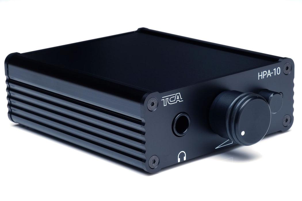
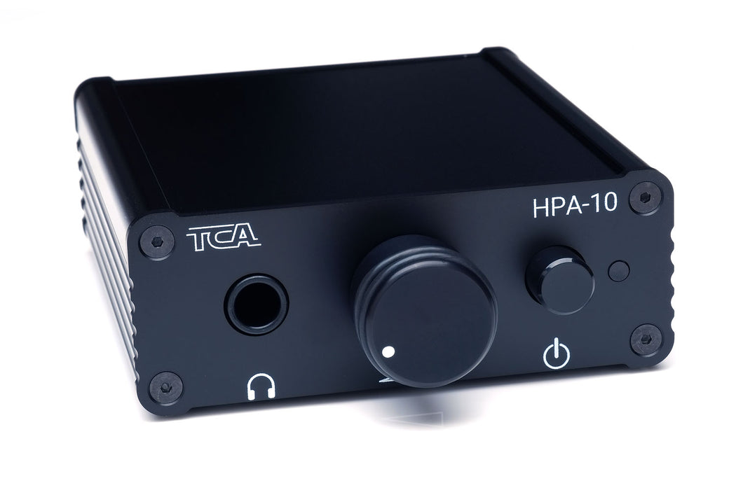
Key Features of the HPA-10
- World class performance as characterized by ultra-low harmonic distortion, extraordinarily low intermodulation distortion, and ultra-low noise floor.
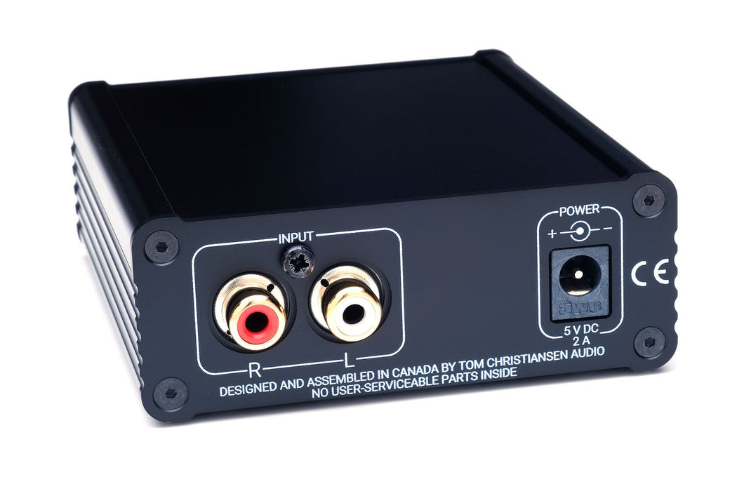
- Input: RCA (unbalanced).
- Output: ¼" (6.3 mm) phone jack.
- Gain: +10 dB (3.2×).
- ALPS RK097 volume potentiometer.
- Mute circuit which prevents clicks and pops in your headphones when the power is turned on and minimizes pops when the power is turned off.
- Protection against excessive DC voltage on the amplifier output. This protects your headphones in the case of a catastrophic amplifier failure.
Output Power
The HPA-10 provides 1.25 W into 32 Ω and 250 mW into 300 Ω. This is plenty to reach ear-splitting levels with the vast majority of headphones on the market.
Ultra-Low Distortion
I firmly believe that audio components should have as little impact on the sound quality as possible. This is why I optimize all TCA designs for the lowest possible distortion. The low total harmonic distortion (THD) and intermodulation distortion (IMD) of the HPA-10 result in a realistic, engaging, and fatigue-free listening experience.
Ultra-Low Noise
The total noise of the HPA-10 measures 1.6 µV RMS (A-weighted) within the audio band. This results in a dynamic range of 130 dB and a signal-to-noise ratio of 131 dB. To put this into perspective, 130 dB is the dynamic range from the quietest perceptible sound to the threshold of pain! Due to this enormous dynamic range, the HPA-10 will allow you to experience an incredible level of detail, both in the quietest passages and in the crescendos of the music.
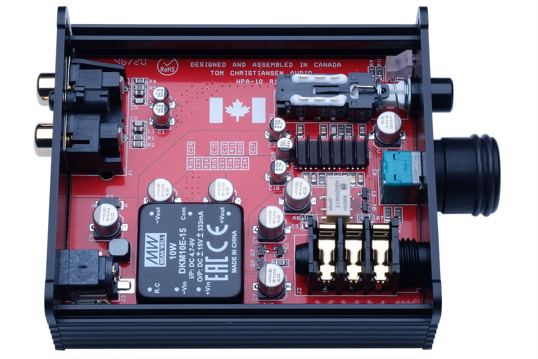
Designed, Assembled, and Tested in Canada
The HPA-10 is designed, manufactured, and tested in Canada. The raw circuit board is made in Ontario. The circuit assembly and test are performed in Calgary. The chassis is made in Japan. The electronic components are sourced from authorized distributors in the USA and Canada.

Outline
Total Harmonic Distortion (THD)
The graph below shows the THD+N vs output power with 300 Ω load. The amplifier delivers 260 mW at the onset of clipping. Note that the sharp jumps (aside from when the amplifier clips) are caused by range switching in the Audio Precision APx525 audio analyzer used for the measurement. The THD+N vs output power plots mostly show the THD+N floor of the measurement system.

Similarly, the THD+N vs frequency shows a fairly flat response. This is no surprise as the measurement is limited by the noise of the APx525 instrument.

The distortion of the HPA-10 does start to creep up a bit when a 32 Ω load is used as seen below. It should be noted that the distortion is nearly two orders of magnitude below audible at all power levels below clipping.

The graph below shows the THD+N vs frequency for 100 mW into 32 Ω.

Intermodulation Distortion (IMD)
Single-tone distortion tests, such as THD+N measurements, are useful to determine fundamental amplifier performance and behaviour. However, some criticize these tests as being too simplistic to properly describe the amplifier's behaviour when presented with a more complex signal such as music.
Intermodulation tests address this by using two or more test tones. The gold standard among these tests is the 32-tone test developed by Audio Precision. I was among the first to use this test for amplifier characterization and other vendors have started to follow suit.
The Audio Precision 32-tone IMD test uses 32 test tones of equal amplitude logarithmically spaced in frequency. The phase of the test tones have been designed to provide a crest factor of 10 dB, which is quite representative of music. The signal itself sounds a bit like an out of tune pipe organ.
The graph below shows the result of the 32-tone IMD test with the HPA-10.

The combined amplitude of the 32 tones is the 0 dB reference, and corresponds to 100 mW into 300 Ω. The intermodulation products - i.e. the "grass" between the test tones - are distortion products from the amplifier. These should be as low as possible. As seen in above graph, these distortion products are more than 140 dB (10,000,000×) lower than the reference level, which is truly stellar. This indicates that even with a complex input signal the HPA-10 does not add any audible colouration to the input signal. It is a truly transparent amplifier. The transparency of the HPA-10 is seen in the two-tone IMD tests as well.
Siegfried Linkwitz has proposed a 1 kHz + 5.5 kHz IMD test, which he argues to be highly indicative of the perceived sound quality. He bases his argument on the fact that IMD products in this measurement fall in the frequency range where the ear is the most sensitive (see the Fletcher-Munson curves for more detail). This seems like a reasonable argument so I measured the HPA-10 accordingly.
The result of this measurement is shown below. Note that due to a limitation in the signal source of the APx525, the frequencies used must be an integer multiple of each other. Thus, my test signal consisted of 917 Hz (5500/6) and 5.5 kHz at equal amplitude. I performed this measurement at 1.0 mW as this is representative of typical listening levels with most headphones. The result is shown below.

The IMD products are buried in the noise floor of the measurement equipment. Excellent!
The two more traditional IMD measurements are the SMPTE 60 Hz + 7 kHz (4:1 amplitude ratio) and the 18 kHz + 19 kHz (1:1 amplitude ratio). The former is often used to tease out thermal issues within the amp. The latter often reveals lacking loop gain (so basically lack of control) towards the higher end of the audio frequency range.
The SMPTE IMD test result for the HPA-10 is shown below.

Only the second (d2) and third (3d) order IMD product extend above the noise floor.
The result of the 18+19 kHz IMD measurement for the HPA-10 is shown below. Only the second and third order IMD product (2d and 3d) extend above the noise floor.

Noise
The total integrated noise measures 1.7 µV (A-weighted). The HPA-10 shows no residual mains hum. This is what a quiet amp looks like!

Amplitude Response, Channel Separation, Etc.
For completeness I measured the amplitude response and gain flatness of the HPA-10. The results are shown below.


The measurement below shows the amount of crosstalk between the left and right channels in the HPA-10. As seen in the graph, the crosstalk is lower than -100 dB across the majority of the audio band. This corresponds to a channel separation of 100 dB.

Transient Response
The measurements above all characterize the amplifier in the frequency domain. Transient response measurements describe how the amplifier performs in the time domain.
Amplifier stability is paramount and achieving good stability in an amplifier featuring a high-speed composite output stage can be a significant challenge. Therefore, I characterized the transient behaviour of the HPA-10 for various reactive loads.
The oscilloscope images below shows the transient response of the HPA-10 when presented with a 10 kHz square wave and loaded by 300 Ω in parallel with 470 pF of capacitance. This load is representative of a pair of Sennheiser HD-650 with the stock cable and a 2-3 m (~10') extension cord.

As shown above, the transient response of the HPA-10 is exemplary.
Increasing the capacitance to 1.0 nF (Sennheiser HD-650 with the stock cable and an 8 m (~26') extension cord) still shows a clean response.

With 4.7 nF (Sennheiser HD-650 + stock cable + 45 m (~147') extension cord), a very slight degradation of the transient response is observed as a little bit of overshoot develops. The amplifier still shows no signs of instability as no ringing is present in the measurement.

Finally, when loaded with 10 nF, the amplifier finally shows some overshoot and ringing. Note, however, that to obtain such capacitive load in actual use would require approximately 100 m (300') of extension cable on a typical pair of headphones. It is also noteworthy that the HPA-10 remains stable even with 100 nF capacity load. Needless to say, I have full confidence in the stability of the HPA-10.

Clipping Behaviour
The HPA-10 is a composite amplifier as it uses a precision opamp to provide error correction on a less precise output stage. In addition to stability, one of the main challenges in the design of a composite amplifier is to ensure that the amplifier recovers cleanly from clipping.
The clipping response of the HPA-10 is shown below. The first graph shows the amplifier output when driven just below clipping. The second graph shows the amp's response to a slight overdrive (soft clipping). The final graph shows the amplifier's output when clipping hard. As seen in the images, the HPA-10 recovers cleanly from clipping without any tendency to oscillate. Excellent!