-
The key features of the LM3886DR are summarized below.
- LM3886 layout fully optimized for high signal integrity.
- All components needed for good amplifier stability included in the circuit.
- Elaborate use of planes and pours to minimize ground bounce and ensure good THD performance across the audible frequency spectrum for the best audio quality possible.
- Input RFI/EMI filter prevents all pops and clicks from the switching of heavy loads as well as buzz associated with cell phones, WiFi, and other RF interference sources.
- Mono board to allow for mono block construction. Two boards are needed for a stereo build.
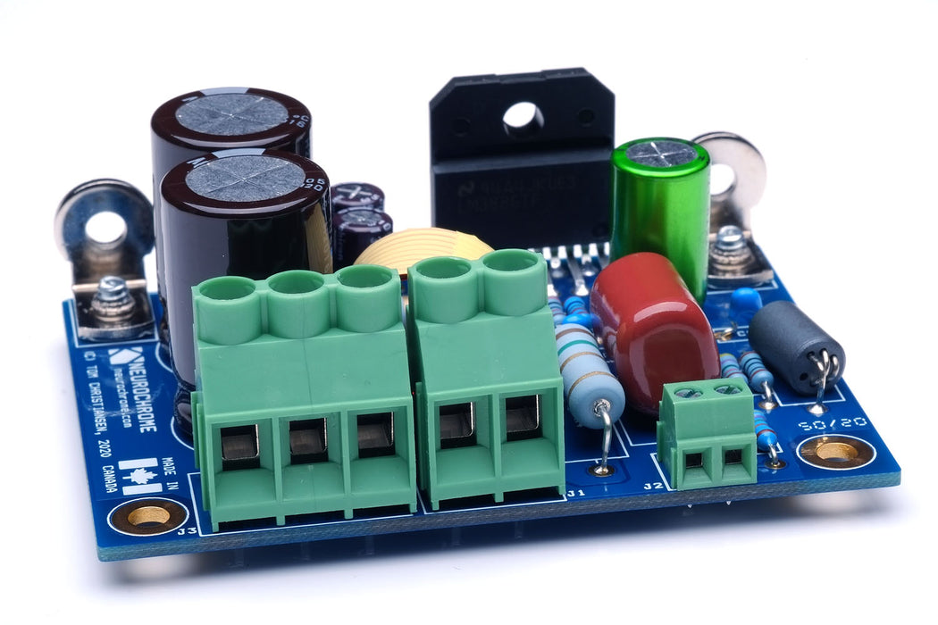
- On-board mounting brackets for attachment to heat sink.
- Terminal blocks accepting up to 10 AWG (5 mm²) wires are used for the power supply and speaker connections.
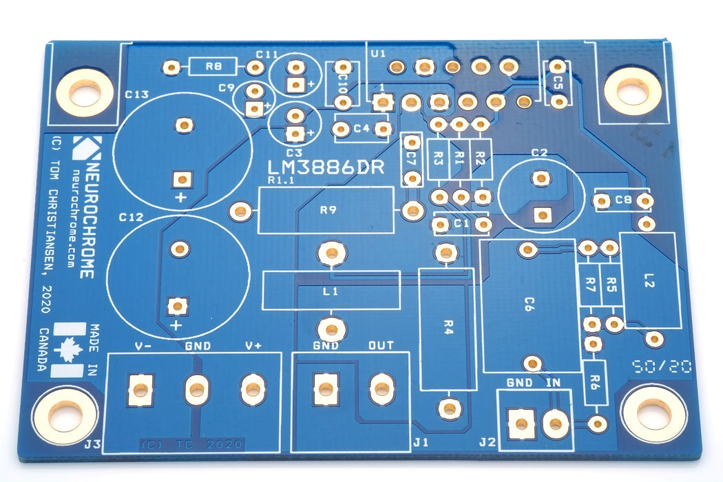
- 3.00 x 2.20 inch board size (76 x 56 mm) with mounting holes suitable for machine screws up to 3.8 mm in diameter (UNC #6-32).
- Gold plated circuit board. Made in Canada and fully electrically tested by the manufacturer.
- 25+ page detailed design documentation provided with the board. The documentation includes a link to a project set up with Mouser Electronics for ease of ordering.
Build budget: The cost of parts for the LM3886DR is just shy of $25 per board. In addition to the parts listed in the project set up with Mouser, you will need 50 cm of AWG 18 (1.0 mm diameter) enamelled magnet wire to make the output inductor. Solid core insulated AWG 20 hookup wire may be used in a pinch. Alternatively, I do offer ready-made inductors should you prefer a professionally made part. You will also need some thermally conductive paste (Wakefield #120, Arctic Silver, et al.) and a heat sink for the LM3886.
The biggest cost drivers are the enclosure and power supply. For enclosures, ModuShop in Italy offers excellent products at a very reasonable cost. Some of their products are available through the DIY Audio Shop. The 2U tall Dissipante series would work well with up to a 4-channel LM3886DR. For the power supply, I recommend a Power-86.
-
The simplified schematic of the LM3886DR is shown below.

The RFI/EMI filter on the input of the amplifier prevents the annoying clicks and pops from the switching of heavy loads, such as refrigerators, electric furnaces, and the like. It also removes the interference caused by cell phones, WiFi routers, and such to allow for the best audio performance.
Observant readers will recognize the noise gain compensation applied at the inputs of the LM3886. This compensation is necessary to avoid quasi-oscillation near clipping and is necessary to get the full rated output power from the LM3886. A series RC network is added in the feedback path to ensure a clean and fast transient response of the LM3886DR. A snubber or Zobel network (R+C) and Thiele network (L || R) are added on the output to ensure good amplifier stability even with a capacitive load.
-
The full set of specifications for the LM3886 Done Right are tabulated below.
| Parameter |
Value |
Notes |
| Output Power |
45 W |
8 Ω, THD+N < 0.1 % |
| THD |
-96.5 dBc
0.0015 %
|
1 W, 8 Ω, 1 kHz |
| THD |
-97.5 dBc
0.0013 %
|
45 W, 8 Ω, 1 kHz |
| THD+N |
-95.4 dBc
0.0017 %
|
45 W, 8 Ω, 1 kHz, 20 kHz BW |
| Output Power |
75 W |
4 Ω, THD+N < 0.1 % |
| THD |
-89.6 dBc
0.0033 %
|
70 W, 4 Ω, 1 kHz |
| THD+N |
-88.6 dBc
0.0037%
|
70 W, 4 Ω, 1 kHz, 20 kHz BW |
| IMD: SMPTE 60 Hz + 7 kHz @ 4:1 |
-84.5 dBc
0.0060 %
|
45 W, 8 Ω |
| IMD: DFD 18 kHz + 19 kHz @ 1:1 |
-97.3 dBc
0.0013%
|
45 W, 8 Ω |
| Multi-Tone IMD Residual |
-112 dB ref. 45 W, 8 Ω |
AP 32-tone, 45 W, 8 Ω |
| Gain |
26.0 dB |
|
| Input Sensitivity |
950 mV RMS |
45 W, 8 Ω |
| Bandwidth |
2.4 Hz – 90 kHz |
1 W, 8 Ω, -3 dB |
| Slew Rate |
±16.5 V/µs |
8 Ω || 1 nF load |
| Total Integrated Noise and Residual Mains Hum |
29 µV |
20 Hz - 20 kHz, A-weighted |
| Total Integrated Noise and Residual Mains Hum |
38 µV |
20 Hz - 20 kHz, Unweighted |
| Dynamic Range (AES17) |
> 112 dB |
1 kHz |
Signal-to-Noise Ratio
|
114 dB
|
1 kHz, 45 W, 8 Ω |
SINAD
|
101 dB
|
5 W, 8 Ω, 1 kHz
|
| All parameters are measured using a ±30 V regulated power supply unless otherwise noted. |
-
The performance measurements of the LM3886 Done Right are shown below. The THD+N vs output power matches the performance specified in the LM3886 data sheet.

The THD+N vs frequency is shown below. The performance of the LM3886DR is actually better than the data sheet performance of the LM3886! This speaks volumes to the quality of the layout of the LM3886DR.

Repeating these measurements with a 4 Ω load provides the following results. As expected, the THD+N is slightly higher for a 4 Ω load.


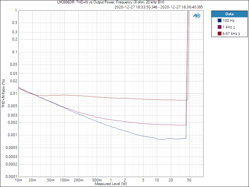
The THD+N versus frequency plots above were both measured with a 60 kHz measurement bandwidth to include at least three harmonics of 20 kHz. However, in particular for Class D amplifiers, it has become increasingly common with measurements of THD+N versus output power at three frequencies: 100 Hz, 1 kHz, and 6.67 kHz. This allows for capturing at least three harmonics of all test frequencies within a 20 kHz measurement bandwidth. I measured the LM3886DR accordingly and the result is shown below.
The THD at 1 W output into an 8 Ω load is quite low as seen in the harmonic spectrum below. It is interesting to note the mains-related IMD spectral components. At nearly 110 dB below the fundamental signal, they're hardly an issue. Just an interesting testament to the power supply rejection of the LM3886.

The mains hum itself is actually very low as shown in the graph below.

The multi-tone IMD is shown below. The tallest offender checks in 112 dB below the peak of the signal, which was set to provide 45 W into 8 Ω.

The 18 kHz + 19 kHz (1:1) two-tone IMD test is often used as an indicator of the loop gain available at 20 kHz. As shown below, the IMD of the LM3886DR is quite good.

The 60 Hz + 7 kHz SMPTE IMD, on the other hand, is often used to tease out thermal issues in the amplifier. As shown below, the LM3886DR passes with flying colours.

Siegfried Linkwitz argues that the 1 kHz + 5.5 kHz intermodulation distortion (IMD) measurement is one of the measurements which is more indicative of the perceived sound quality. He bases this argument on the fact that IMD products in this measurement fall in the frequency range where the ear is the most sensitive (see the Fletcher-Munson curves for more detail). I think this argument carries a good amount of weight, so I measured the LM3886DR accordingly. The measurement is shown below. Note that due to a limitation in the DFD IMD source of the APx525, the frequencies used must be an integer multiple of each other. Thus, I measured at 917 Hz (5500/6) + 5.5 kHz. I performed this measurement at 1.0 W. The result is shown below.

Finally I measured the gain and gain flatness within the audio range. As seen below, the gain is very flat, with a slight rolloff towards the upper end of the audio band.