
As you have probably noticed, my reviews are free of advertising. Instead of distracting you with annoying ads, I kindly request your donation. If you find the contents of this page to be useful, please consider making a donation by clicking the Donate button below.
MiniDSP 4x10 HD
The MiniDSP 4x10 HD is commonly used with multi-channel open baffle or dipole speakers, such as the Linkwitz Orion, LX521, and LXmini. It is a quite capable box. While there is room for improvement, in particular in the output stages, the MiniDSP 4x10 HD does provide a quite reasonable level of performance given its price point.
"4x10" refers to the four inputs and ten outputs. Do note that the terminology, while common in the professional audio world, can be a little tricky at first.
The four inputs are: Two analog (left + right channels if configured for stereo), optical (TOSLINK), and coax/AES (S/PDIF). In other words, the MiniDSP 4x10 HD accepts one stereo input. This one stereo input can come from one of three sources: analog, optical, or coax/AES.
Similarly, the ten outputs are: Eight analog (= four stereo outputs if configured as such), optical (TOSLINK), and coax/AES (S/PDIF). Thus, the MiniDSP 4x10 HD can drive two 4-way speakers in a stereo setup.
The guts of the MiniDSP 4x10 HD are:
- DAC: Cirrus Logic CS42528.
- DSP: Analog Devices ADAU1445.
- The I/O opamps: JRC2068, which is the same as NJM2068.
I would have liked to see a better opamp, such as the OPA1611, used but considering the number of opamps needed, I do understand MiniDSP's decision to stick with the JRC parts. Unfortunately, the opamps are in a surface mounted "DMP8" package and not the vastly more common SOIC-8 or SSOIC-8 packages, so they can't be swapped out by the end user, even if the end user has SMD soldering capabilities. I suspect the DMP8 package is a JRC proprietary package.
Performance Measurements
All measurements were performed using the balanced analog input, all filters in the MiniDSP set to bypass, and the MiniDSP volume control disabled. Unless otherwise noted, the measurement bandwidth is 20 kHz (AES17) using the 44.1 kHz sampling ADC in the Audio Precision APx525. This ADC is the lowest noise of the three ADCs in the APx525.
A common comment in various forums is that the MiniDSP is "noisy" and I suspect this noise comes from the analog I/O blocks. While it could probably be improved by some optimization of those blocks, the noise level is really quite low. Integrated over 10 Hz to 20 kHz (AES17 filter), I measured 26.5 µV RMS on the differential (balanced) output at the 4.0 V gain setting. Comparing that with the 21.0 µV RMS I measure on my Differential Preamp 8x2 which uses state-of-the-art line drivers and line receivers from THAT Corp., the MiniDSP is really doing quite well. The output noise spectra for the MiniDSP 4x10 HD for balanced/unbalanced at the low/high gain settings are shown below.
From the noise plot below, I conclude that if you are using the balanced outputs, use the low gain setting (4.0 V). However, if you are using the unbalanced outputs, use the high gain setting (2.0 V). These settings will result in the best SNR and gain structure for your setup.

The noise is evident in the THD+N vs output level plot shown below.

There's a bit of noise outside the audio band as well. The DAC is clearly applying some noise shaping. Fair enough. After all, it's the noise within the audio band that we're concerned with for audio reproduction.

The intermodulation distortion (IMD) was tested using an Audio Precision 32-tone test signal. This signal uses tones of equal amplitude logarithmically distributed in frequency starting at 16 Hz and ending at 20 kHz. The multi-tone IMD of the MiniDSP is quite nice. It's about 15-20 dB higher than that of my Differential Preamp 8x2, so reasonably close to state-of-the-art.

The THD (no +N) plot below was measured using a precision 1 kHz oscillator. The THD of the oscillator itself is -145 dB, thus the THD shown in the plot below is purely from the MiniDSP. Do note that the mains hum evident at 60, 120, 240 Hz as well as a the 60 Hz IMD around the 1 kHz fundamental are caused by the oscillator.

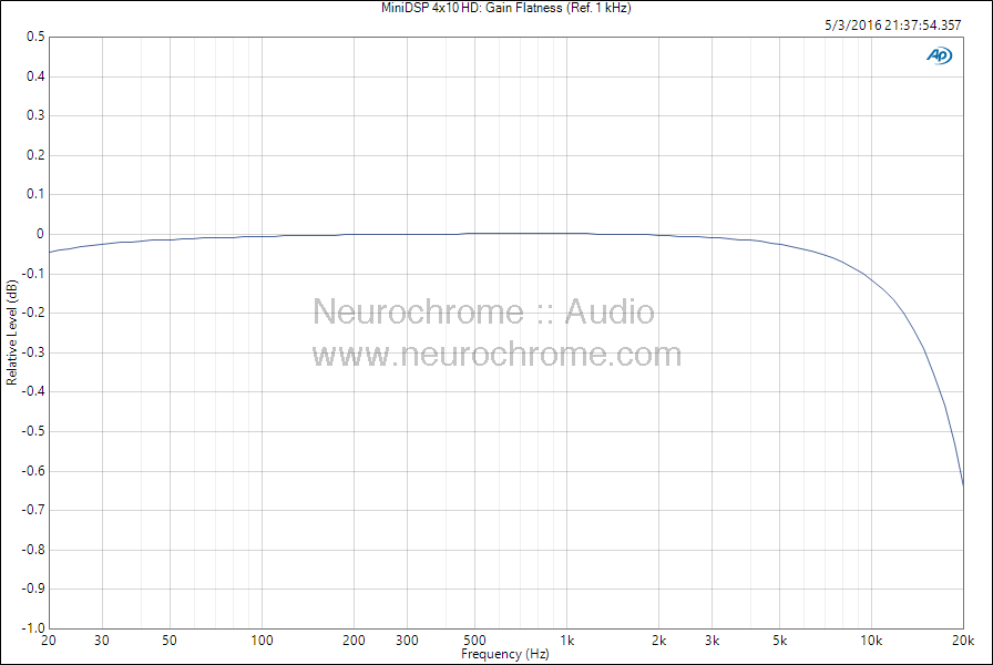
The remaining plots should not require much introduction and I will let them speak for themselves.


The common-mode rejection ratio (CMRR) is the only parameter that I find a bit lacklustre on the MiniDSP 4x10 HD. They appear to be using ±1 % or possibly ±0.5 % tolerance resistors, so the CMRR is better than 40 dB up to approx. 2 kHz. The rise in CMRR above 500 Hz is likely caused by the mismatch between the two inductors in the input RFI/EMI LC filter. That said, the CMRR of the MiniDSP 4x10 HD is much better than the 0 dB CMRR you'd get from an unbalanced input. 
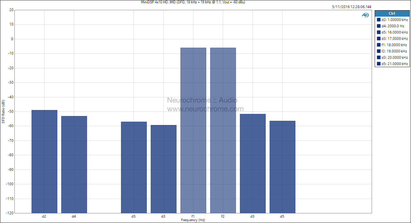
Measurements at Low Output Level
The following measurements were performed at -60 dBu output voltage. This was accomplished by reducing the input voltage until the output voltage reached -60 dBu. 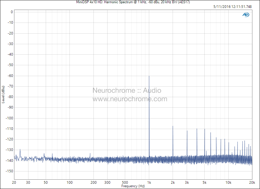


Please Donate!
Did you find this content useful? If so, please consider making a donation by clicking the Donate button below.